
MQ135
Air Quality Gas Sensor
Low-cost SnO₂ semiconductor gas sensor for air-quality monitoring, with sensitivity to ammonia, sulfide, benzene-series vapors, hydrogen and smoke.
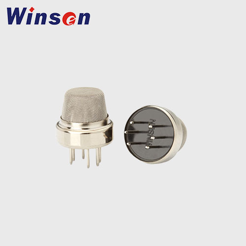
Reliable air-quality sensing with a simple drive circuit.
In clean air, the MQ135 sensing material has lower conductivity. When pollution gases are present, conductivity increases with gas concentration, allowing a simple circuit to convert the change into an output signal.
Applications
Suitable for domestic gas alarms, industrial gas alarms, portable gas detectors and general air-quality monitoring products.
sales@winsensor.com · www.winsen-sensor.com · +86-371-67169097 / 67169670

 Scan for
technical support
Profile, Features and Sensor Structure
Product profile
The sensitive material of the MQ135 gas sensor is SnO₂, which has lower conductivity in clean air. When a target pollution gas is present, sensor conductivity increases as gas concentration rises. A simple external circuit converts this conductivity change into a corresponding output signal.
MQ135 has high sensitivity to ammonia, sulfide and benzene-series vapors. It can also monitor hydrogen, smoke and other toxic gases, making it a cost-effective option for multiple air-quality applications.
Key features
Wide toxic-gas sensitivity range, long service life, low cost and a simple drive circuit.
Main applications
Domestic gas alarms, industrial gas alarms and portable gas detectors.
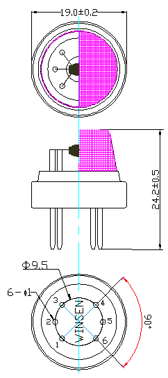
Technical Parameters and Standard Test Conditions
| Category | Parameter | Specification |
|---|---|---|
| General | Model | MQ135 |
| General | Sensor type | Semiconductor |
| General | Standard encapsulation | Bakelite base with metal cap |
| General | Target gases | Ammonia gas, sulfide and benzene-series vapors |
| General | Detection range | 10–1000 ppm for ammonia gas, toluene, hydrogen and smoke |
| Standard circuit conditions | Loop voltage VC | 5.0V ± 0.1V DC |
| Standard circuit conditions | Heater voltage VH | 5.0V ± 0.1V AC or DC |
| Standard circuit conditions | Load resistance RL | Adjustable |
| Sensor characteristics | Heater resistance RH | 30Ω ± 3Ω at room temperature |
| Sensor characteristics | Heater consumption PH | ≤950mW |
| Sensor characteristics | Sensitivity S | RS(in air) / RS(in 400 ppm H₂) ≥ 5 |
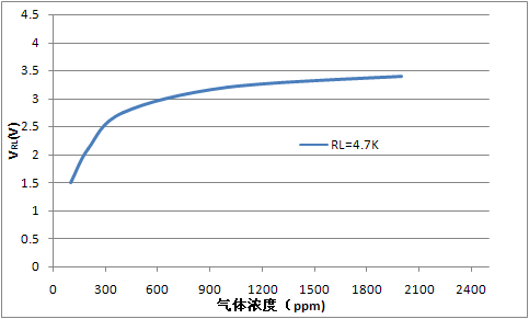
| Sensor characteristics | Output voltage VS | 2.0V–4.0V in 400 ppm H₂ |
| Sensor characteristics | Concentration slope α | ≤0.6, R400ppm / R100ppm in H₂ |
| Standard test conditions | Temperature and humidity | 20°C ± 2°C; 55%RH ± 5%RH |
| Standard test conditions | Standard test circuit | VC: 5.0V ± 0.1V; VH: 5.0V ± 0.1V |
| Standard test conditions | Preheat time | Over 48 hours |
| Environment | Oxygen content | 21%; not less than 18%. Oxygen concentration affects the initial value, sensitivity and repeatability. |
| Service life | Lifespan | 10 years under specified operating conditions |
Basic Test Circuit and Calculation Formulas
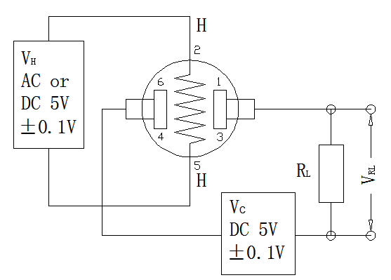
Circuit instructions
The MQ135 requires two voltage inputs: heater voltage VH and circuit voltage VC. VH establishes the standard working temperature of the sensing element and may use AC or DC power.
VRL is the voltage across load resistance RL, which is connected in series with the sensor. VC supplies the detection voltage to RL and must use DC power.
Calculation formulas
PS = VC2 × RS / (RS + RL)2
Note: Output voltage VS is VRL in the test environment.
Sensitivity, Temperature/Humidity, Response and Stability
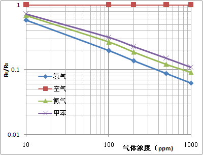
Typical sensitivity curve
The ordinate represents the sensor resistance ratio RS/R0. R0 is the sensor resistance in the specified reference condition. Oxygen content is 21% and must not be below 18%.
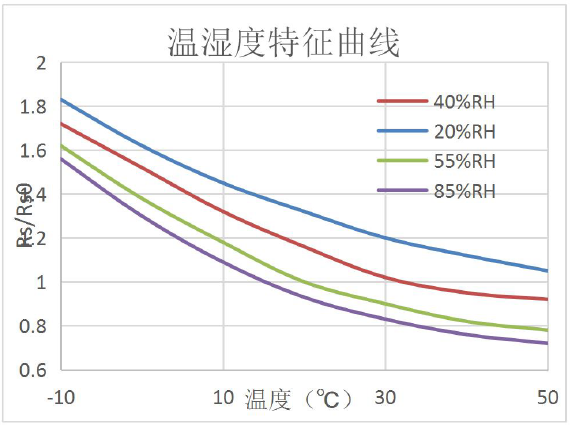
Temperature / humidity
The ordinate is RS/RSO. RS is resistance in 400 ppm H₂ at different temperatures and humidities; RSO is resistance in 400 ppm H₂ at 20°C/55%RH.
Dynamic characteristics
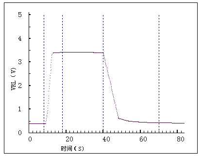
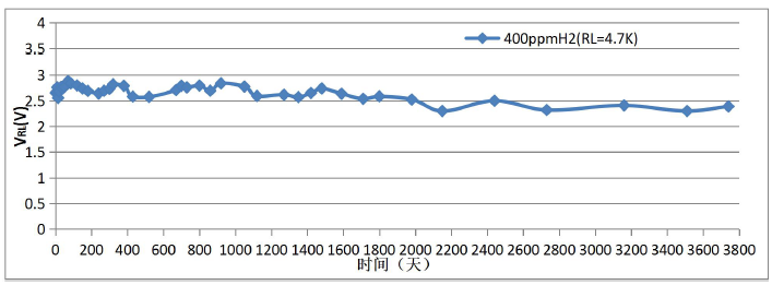
Figure 5 uses RL = 4.7kΩ under standard test conditions. Figure 6 shows the VRL change as the sensor enters and leaves the target gas. Figure 7 records long-term output stability.
Conditions That Must Not Be Applied
- Organic silicon vapor. Silicone compounds can permanently reduce sensitivity. Keep the sensor away from silicone bonds, fixtures, silicone latex, putty and plastics containing silicone.
- Highly corrosive gases. High concentrations of H₂S, SOx, Cl₂, HCl and similar gases can corrode the structure and cause serious sensitivity attenuation.
- Alkali, alkali-metal salts and halogens. Brine, alkali-metal salts, fluorine and similar contamination can severely change sensor performance.
- Water contact. Splashing or immersion reduces sensitivity.
- Freezing. Prevent icing on the sensing surface; freezing can damage the sensing material and cause sensitivity loss.
- Excess voltage. Do not apply a voltage above the specified value. Excess voltage can damage the lead or heater and seriously alter sensitivity.
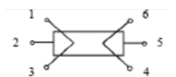
- Incorrect pin voltage. For the 6-pin sensor, pins 2 and 5 are heater electrodes; pins (1,3) and (4,6) are test electrodes. Incorrect connections may break leads or produce no output.
Conditions to Avoid, Aging Time and Welding Guidance
Water Condensation
Minor indoor condensation may influence performance. Prolonged condensation on the sensing surface can reduce sensitivity.
High Gas Concentration
Long exposure to a high gas concentration may affect characteristics whether the sensor is powered or not. Direct lighter-gas spray may cause serious damage.
Adverse Environment
Long exposure to high humidity, high temperature or heavy pollution can negatively affect performance.
Vibration
Continuous vibration can weaken or break sensor leads. Pneumatic screwdrivers and ultrasonic welding equipment may introduce damaging vibration.
Concussion
Strong impact may disconnect internal lead wires.
Long-Term Storage
Store in an airtight bag without volatile silicone compounds. Resistance drift after storage is reversible but requires adequate electrical aging before use.
| Storage Time | Suggested Aging Time |
|---|---|
| Less than one month | No less than 48 hours |
| 1–6 months | No less than 72 hours |
| More than six months | No less than 168 hours |
Recommended manual soldering conditions
Manual soldering is the preferred assembly method. Use lead-free, halogen-free soldering flux and a temperature-controlled soldering iron. Soldering temperature must not exceed 350°C, and soldering time must be less than 3 seconds. Failure to follow these conditions may reduce sensor sensitivity.
Zhengzhou Winsen Electronics Technology Co., Ltd.
Tel: +86-371-67169097 / 67169670
Fax: +86-371-60932988
E-mail: sales@winsensor.com
Website: www.winsen-sensor.com