Smart Secondary Water Supply Pump Room Monitoring: Pressure, Level and Environmental Sensing
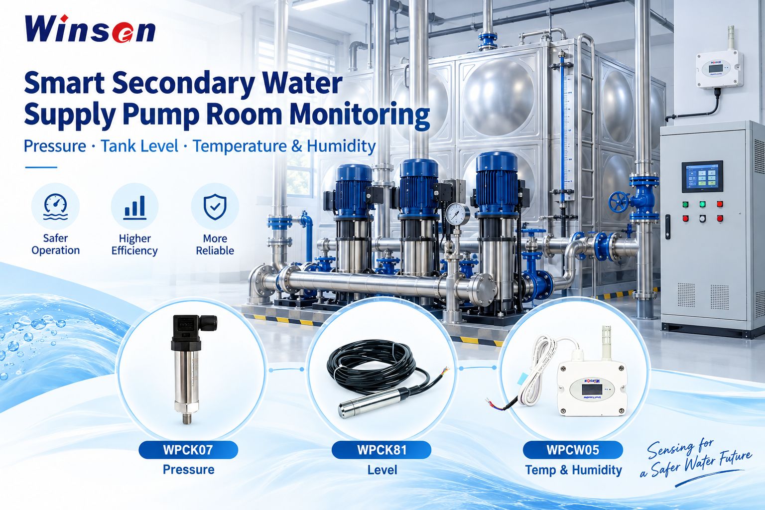
Secondary water supply systems, often described internationally as building water booster systems or booster pump systems, are widely used in residential communities, commercial buildings, hospitals, schools, industrial parks and other facilities where municipal water pressure alone cannot meet building demand.
A typical pump room may already contain booster pumps, variable-frequency drives, PLCs, control cabinets, storage tanks, valves and basic protection functions. The challenge is often not the absence of control equipment, but that important operating conditions are still distributed across different instruments and are difficult to monitor continuously from one system.
For many projects, a practical smart upgrade therefore does not mean replacing the existing PLC, VFD or safety interlocks.
A more realistic approach is:
Keep the existing control system, add the sensing data that is missing, and connect that data to the existing monitoring architecture.
For the sensing layer, three parameters provide a practical foundation:
Pressure — for pump and pipeline operating conditions
Tank level — for water storage status
Temperature & humidity — for the pump room environment
Winsen supports these three monitoring tasks with:
WPCK07 Pressure Transmitter
WPCK81 Liquid Level Transmitter
WPCW05 Temperature & Humidity Transmitter
What Is a Secondary Water Supply Pump Room?
A secondary water supply system is generally used when incoming municipal water pressure cannot directly maintain the pressure or flow required by the building water network.
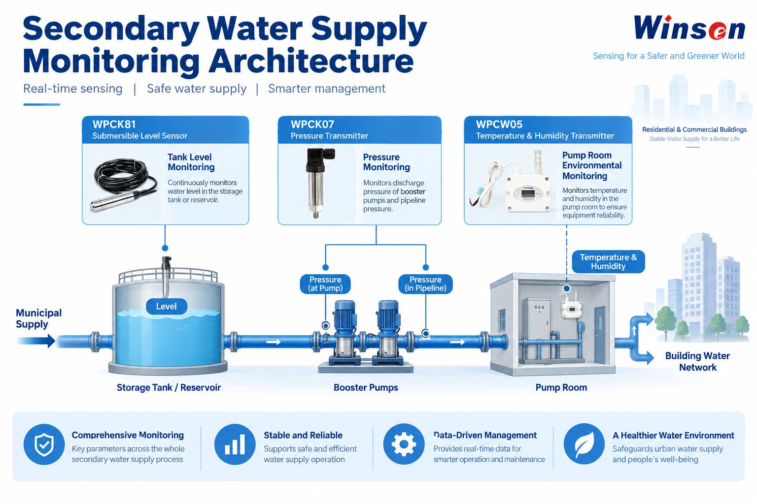
A simplified system can be represented as:
Municipal Water Supply → Storage Tank / Reservoir → Booster Pumps → Building Water Network
The pump room acts as the operating center of this process.
Depending on the project, it may contain water tanks, booster pumps, piping, valves, pressure instruments, variable-frequency drives, PLCs, electrical cabinets and other monitoring or safety equipment.
For an intelligent monitoring system, the objective is not simply to know whether a pump is ON or OFF.
Operators also need to understand:
- whether the hydraulic pressure is changing abnormally;
- whether sufficient water remains in the storage tank;
- whether the pump room environment is changing;
- and whether these data can be collected, recorded and used by the existing management system.
What Should Be Monitored in a Secondary Water Supply Pump Room?
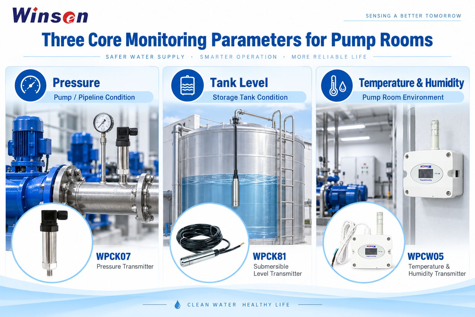
For a basic secondary water supply monitoring system, pressure, tank level and pump room temperature & humidity are three complementary parameters.
They describe different parts of the same operating environment.
| Monitoring Parameter | What It Shows | Winsen Product |
|---|---|---|
| Water pressure | Pump and pipeline hydraulic conditions | WPCK07 |
| Tank level | Water storage condition | WPCK81 |
| Temperature & humidity | Pump room environmental conditions | WPCW05 |
Depending on the scope of the project, a complete smart pump room may also integrate water quality, leakage detection, access control, CCTV, equipment status and energy data.
These additional systems can remain independent or be integrated through the customer's PLC, gateway or upper-level platform.
Winsen's role in this solution is primarily the field sensing layer.
Pressure Monitoring: Understanding Pump and Pipeline Conditions
Pressure is one of the most important hydraulic parameters in a booster water supply system.
Continuous pressure measurement helps operators understand whether the pump and pipeline system is operating within the expected range and provides data for trend analysis, alarms and maintenance decisions.
Typical measurement points include the pump inlet, pump outlet and main supply pipeline.
Pump Inlet Pressure
Pump inlet pressure reflects the hydraulic condition before the booster pump.
When combined with pump operating status and other system information, it provides useful data when evaluating upstream water supply conditions.
Pump Outlet Pressure
The outlet side shows the pressure after boosting.
Monitoring this point can help the system observe:
- pressure changes during pump operation;
- changes during variable-frequency adjustment;
- pressure fluctuations during pump switching;
- and overall supply pressure trends.
Main Supply Pipeline Pressure
The main pipeline represents the pressure being delivered toward the building distribution system.
Continuous measurement at this point helps the monitoring system observe pressure trends and identify abnormal changes that require further investigation.
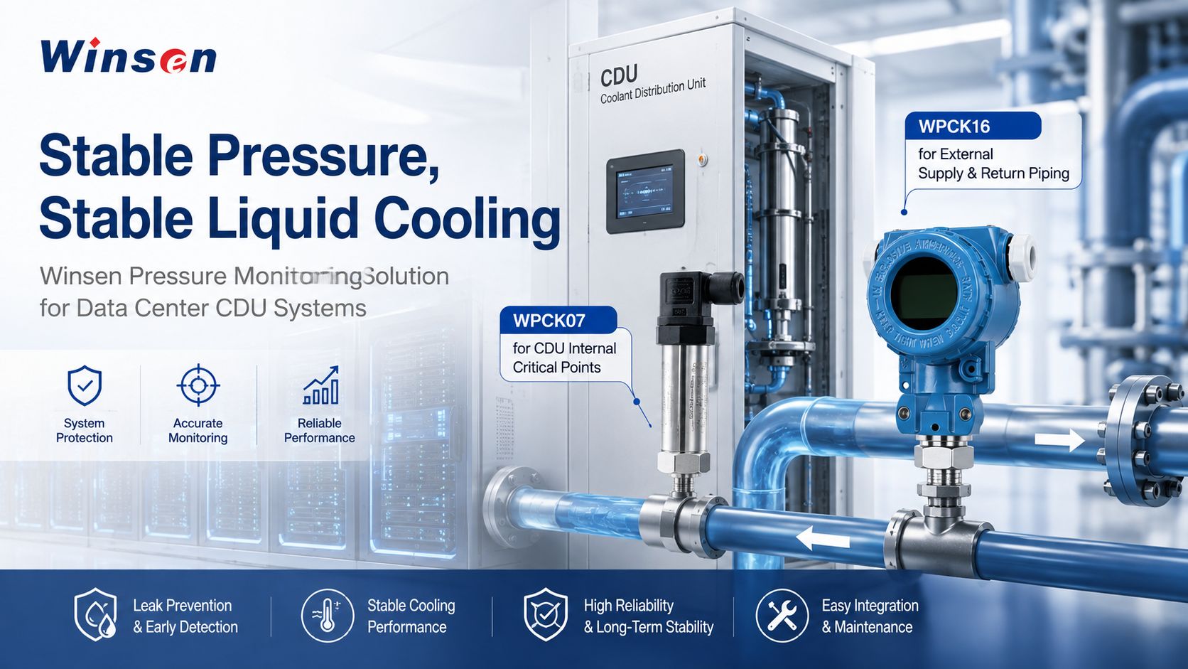
WPCK07 for Water Supply Pressure Monitoring
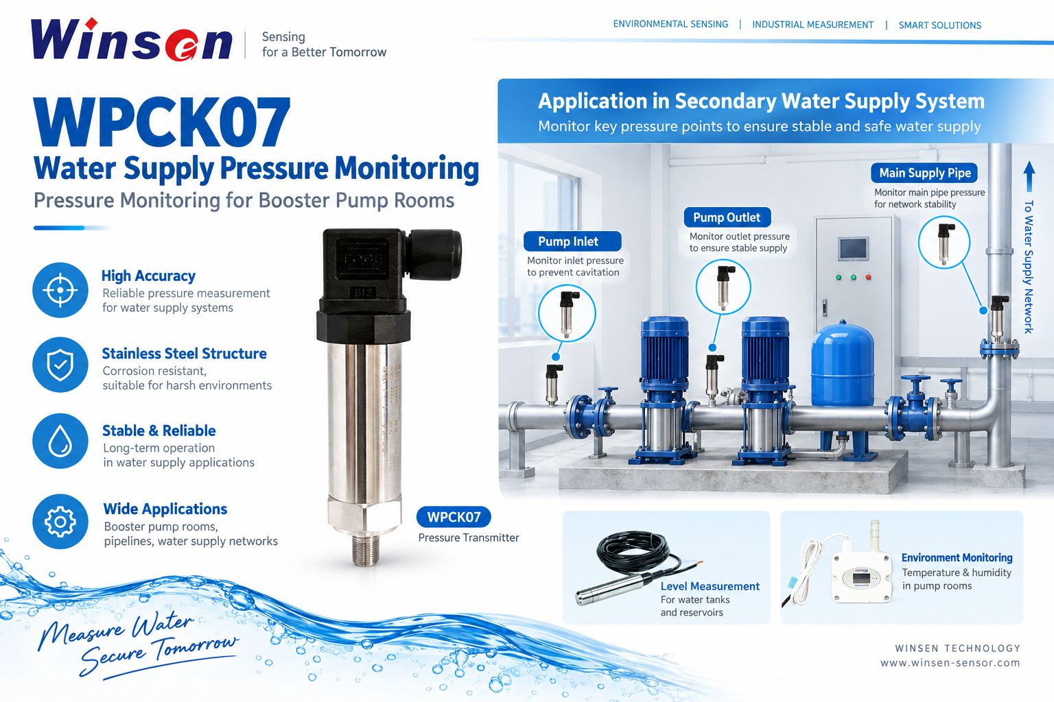
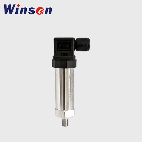
The Winsen WPCK07 is a compact diffused silicon pressure transmitter suitable for equipment and pipeline pressure monitoring.
Its internal circuitry converts the sensing signal into standard electrical outputs that can be connected to PLCs, control instruments and other data acquisition systems.
WPCK07 provides multiple output configurations, including 4–20 mA, several voltage outputs, I²C and RS485, allowing the transmitter configuration to be selected according to the project's controller and communication architecture. The product uses a sealed stainless-steel structure and is designed for industrial pressure measurement applications including pipeline pressure monitoring.
In secondary water supply pump rooms, typical applications include:
- pump inlet pressure;
- pump outlet pressure;
- main supply pipeline pressure;
- and other important hydraulic measurement points defined by the system designer.
The important point is that WPCK07 does not need to replace the existing pump control system.
It provides pressure data to the existing control or monitoring architecture.
For an existing pump room, this makes it possible to add pressure measurement points while continuing to use the original PLC, VFD and control logic.
Tank Level Monitoring: Pressure Cannot Replace Level Measurement
Pipeline pressure and water tank level answer two different questions.
Pressure asks: How is the pressurized water circuit operating?
Level asks: How much water is available in the storage tank?
A pump may temporarily maintain normal outlet pressure even while the water level in the storage tank is decreasing.
For this reason, pipeline pressure should not be used as a substitute for direct tank level measurement.
Continuous level monitoring can provide data for:
- water reserve monitoring;
- low-level identification;
- high-level identification;
- replenishment status observation;
- and historical operation records.
This becomes particularly useful when pump rooms are moving from periodic manual inspection toward continuous monitoring.
WPCK81 for Storage Tank Level Monitoring
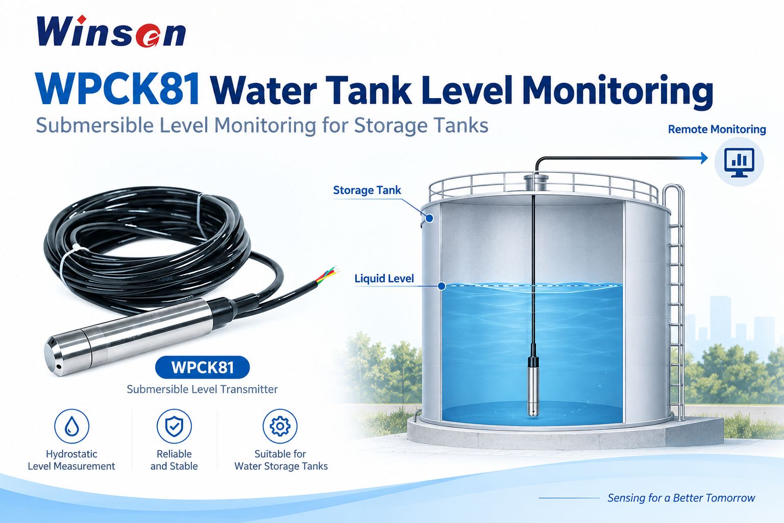
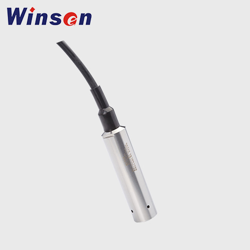
The Winsen WPCK81 is a submersible liquid level transmitter based on piezoresistive pressure sensing.
The probe measures the static liquid pressure associated with water depth and converts it into a signal corresponding to the liquid level.
WPCK81 supports 4–20 mA and RS485 outputs, offers IP68 protection and is designed for applications including liquid tanks, water pools and other static liquid level measurement scenarios.
In a secondary water supply system, the product can be installed in:
- storage water tanks;
- reservoirs;
- or other water storage structures requiring continuous level measurement.
For project selection, parameters such as tank depth, installation method, cable length, required signal output and actual medium should be confirmed according to the system design.
Why Monitor Temperature and Humidity in a Pump Room?
A pump room is not only a hydraulic environment.
It also contains electrical and electronic equipment such as:
- PLCs;
- variable-frequency drives;
- control cabinets;
- communication equipment;
- local displays;
- power supplies;
- and field instruments.
Temperature and humidity data therefore provide useful information about the operating environment around the equipment.
They do not replace dedicated flood detection, electrical protection or equipment diagnostics.
Instead, they provide an additional environmental data layer that can help operators understand how pump room conditions change over time.
For example, long-term humidity trends can be reviewed together with equipment alarms or maintenance records when investigating environmental conditions.
WPCW05 for Pump Room Temperature and Humidity Monitoring
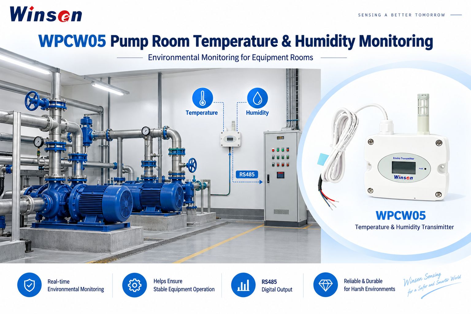
The Winsen WPCW05 uses MEMS temperature and humidity sensing and provides RS485 output for networking and monitoring applications.
The transmitter also incorporates a local display and is designed for temperature and humidity monitoring in building automation, HVAC, industrial environments, data centers and other controlled spaces.
In a secondary water supply pump room, WPCW05 can provide:
- pump room temperature data;
- relative humidity data;
- environmental trend records;
- and an RS485 data source for the PLC or monitoring gateway.
The installation position should represent the general pump room environment rather than a local extreme point.
For example, the transmitter should normally be positioned away from direct water splash, strong local airflow and concentrated heat sources that could affect the representativeness of the measurement.
Recommended Sensor Locations in a Secondary Water Supply Pump Room
A practical monitoring arrangement can be built around the actual hydraulic layout rather than installing the same number of sensors in every project.
| Application Position | Monitoring Parameter | Recommended Product |
|---|---|---|
| Booster pump inlet | Pressure | WPCK07 |
| Booster pump outlet | Pressure | WPCK07 |
| Main supply pipeline | Pressure | WPCK07 |
| Storage tank / reservoir | Liquid level | WPCK81 |
| Representative pump room location | Temperature & humidity | WPCW05 |
For larger systems, additional pressure or environmental points can be added according to the number of pumps, pipe branches, storage tanks and monitoring requirements.
Keep Existing Control, Add the Sensing Data You Need
One of the most practical lessons from existing pump room projects is that smart monitoring does not automatically require rebuilding the entire control system.
Many pump rooms already have a reliable local control foundation.
The PLC can continue to manage pump start/stop logic.
The VFD can continue to control pump speed.
Existing safety interlocks can continue to perform their original protection functions.
The sensing layer can then complement this architecture by adding the data required for continuous monitoring.
A typical data path can be:
WPCK07 Pressure + WPCK81 Level + WPCW05 Temperature & Humidity → PLC / Gateway → Existing Monitoring Platform
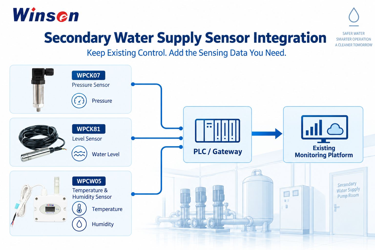
Depending on the project, these data may be transmitted to:
- an existing PLC;
- an edge gateway;
- an HMI;
- SCADA;
- a building management system;
- a smart water management platform;
- or the customer's own monitoring system.
This architecture separates two important responsibilities.
Real-time control remains with the existing control system.
Monitoring data is expanded through additional sensing and data integration.
This makes the approach particularly suitable for existing pump room upgrades.
Existing Pump Room Retrofit vs. New Pump Room
Secondary water supply projects generally fall into several different situations, and the monitoring strategy should reflect the actual project conditions.
Existing Pump Room Retrofit
The first step should be to identify what already works.
A typical existing site may already have:
- PLC control;
- VFDs;
- pump protection;
- local pressure instruments;
- control cabinets;
- and a local HMI.
If these systems continue to meet the required control functions, they do not need to be replaced simply because remote monitoring is being added.
The upgrade can focus on the missing data points.
For example:
Existing PLC + additional WPCK07 pressure measurement + WPCK81 tank level + WPCW05 environmental monitoring
This approach helps reduce unnecessary modification and simplifies integration with the installed system.
New Pump Room
A new project allows the sensing and control architecture to be planned together.
Pressure locations, tank level measurement, environmental monitoring points, output signals, wiring and communication interfaces can all be defined during the engineering stage.
This can make future commissioning and standardization easier.
Multi-Pump-Room Projects
When one representative pump room has been successfully configured and validated, the same measurement-point logic, interface definitions and commissioning process can be used as a reference for similar sites.
This is especially useful for property groups, municipal projects or water supply operators managing multiple pump rooms.
From Monitoring to an Operational Closed Loop
Collecting sensor data is only the first step.
A useful pump room monitoring system should allow the operating team to turn data into actions and records.
A typical operational workflow may include:
Continuous Monitoring → Rule Evaluation → Alarm → Work Order / Handling → Verification → Historical Record
The field sensors provide the underlying measurements.
The PLC, gateway or customer platform determines how these measurements are used.
For example, a project may define:
- pressure thresholds;
- tank level thresholds;
- environmental limits;
- alarm priority;
- notification rules;
- maintenance workflows;
- and historical trend storage.
Winsen sensors provide the field measurement data, while the final control and operational logic remains part of the customer's system architecture.
How Multi-Parameter Monitoring Provides More Context
The value of combining pressure, level and environmental sensing is not simply that the system has more numbers.
The three parameters provide different information.
Falling Tank Level + Stable Pipeline Pressure
The booster system may still be maintaining water supply pressure while available stored water is decreasing.
Tank level therefore provides information that pressure cannot.
Abnormal Pressure + Normal Tank Level
If the water reserve remains normal but the pressure changes significantly, operators can further investigate the pump, valve, pipe or control condition.
High Humidity + Normal Hydraulic Parameters
The water system may still be operating normally while the pump room environmental condition has changed.
That information can be useful for inspection and equipment-room management.
The objective is therefore not to diagnose every fault automatically from three sensors.
It is to give operators a more complete view of pump room status.
Sensor Selection for Secondary Water Supply Projects
Before choosing a configuration, system developers should define several project conditions.
WPCK07 Pressure Selection
Confirm:
- normal operating pressure;
- required measurement range;
- pressure reference;
- pipe connection;
- electrical connection;
- required output signal;
- PLC or gateway interface;
- and medium compatibility.
WPCK07 offers a wide selection of pressure ranges, thread configurations and electrical outputs, which allows the transmitter to be configured for different equipment architectures.
WPCK81 Level Selection
Confirm:
- storage tank depth;
- required measuring range;
- cable length;
- installation position;
- required 4–20 mA or RS485 interface;
- and medium conditions.
WPCW05 Environmental Monitoring
Confirm:
- representative installation location;
- required communication architecture;
- power supply;
- installation environment;
- and whether the local display configuration is required.
Winsen Sensing Layer for Secondary Water Supply Pump Rooms
The core solution can be summarized simply:
| Winsen Product | Main Function | Typical Application |
|---|---|---|
| WPCK07 | Pressure measurement | Pump inlet, outlet and main supply pipeline |
| WPCK81 | Liquid level measurement | Storage tank / reservoir |
| WPCW05 | Temperature & humidity | Pump room environment |
These sensors can form a practical sensing layer covering:
Hydraulic pressure + Water storage + Equipment environment
For OEMs, pump system manufacturers, building water supply equipment suppliers and system integrators, this sensing layer can be adapted to both new projects and existing pump room upgrades.
Frequently Asked Questions
What should be monitored in a secondary water supply pump room?
Pressure, storage tank level and pump room temperature & humidity are three useful core parameters. More comprehensive projects may also integrate water quality, leakage, access control, video, pump status and energy data.
Where should pressure sensors be installed in a booster pump system?
Typical pressure measurement locations include the pump inlet, pump outlet and main supply pipeline. Additional points can be added according to the hydraulic design.
Which Winsen pressure sensor is used in this solution?
This solution uses WPCK07 Diffused Silicon Pressure Transmitter, not the WPCK07DY digital-display version.
Can WPCK07 connect to a PLC?
Yes. WPCK07 provides multiple output configurations, including 4–20 mA, several voltage outputs, I²C and RS485, depending on the selected configuration.
How is water tank level monitored?
A submersible level transmitter such as WPCK81 can be installed in the storage tank. It measures liquid level from hydrostatic pressure and supports 4–20 mA or RS485 output.
Can pipeline pressure replace tank level monitoring?
No. Pipeline pressure represents hydraulic conditions in the pressurized circuit, while tank level represents available water storage. Both measurements provide different information.
Why monitor pump room temperature and humidity?
Temperature and humidity provide information about the operating environment around pumps, control cabinets, PLCs, VFDs and communication equipment. They add environmental context to hydraulic and equipment data.
Does an existing pump room need a new PLC to add these sensors?
Not necessarily. If the existing PLC and control system remain suitable for real-time control, the new sensing points can be integrated with the existing architecture according to the available interfaces.
Build Smart Monitoring Around the Existing Pump Room
For many secondary water supply projects, the most practical path toward smarter operation is not to replace everything.
It is to first identify what is already working, determine which operating conditions are not continuously visible, and then add the required sensing points.
WPCK07 provides pressure data from pumps and pipelines.
WPCK81 provides continuous water storage level data.
WPCW05 provides pump room temperature and humidity data.
Together, they create a sensing foundation that can connect to the customer's existing PLC, gateway or monitoring platform while preserving the original real-time control architecture.
For secondary water supply equipment manufacturers, booster pump system developers and smart water integrators, Winsen can support sensor selection according to the project's pressure range, tank depth, installation conditions, communication interface and system architecture.
Related Winsen Products
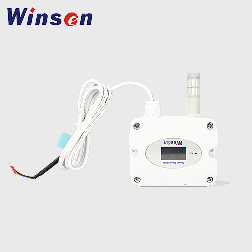
WPCW05 Temperature & Humidity Transmitter
- Temperature: -20~60°C; Humidity: 5%~95%RH (Non-condensing)
- Read More